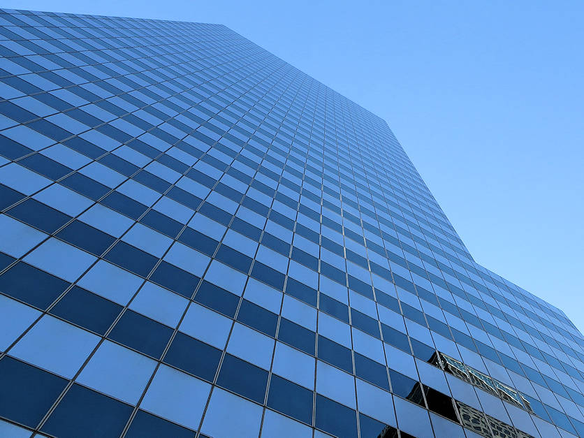
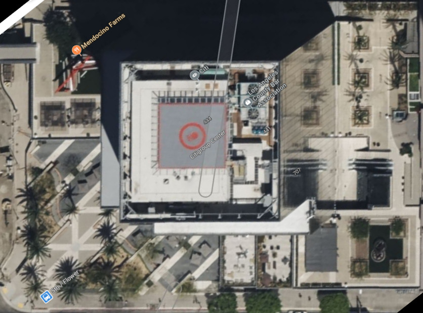
This was a project in 2017 - 2018 at the 444 South Flower high-rise office building located in Los Angeles, CA. The project scope was to design a Communications Head End Equipment Space, serving
a new Distributed Antenna System (DAS).
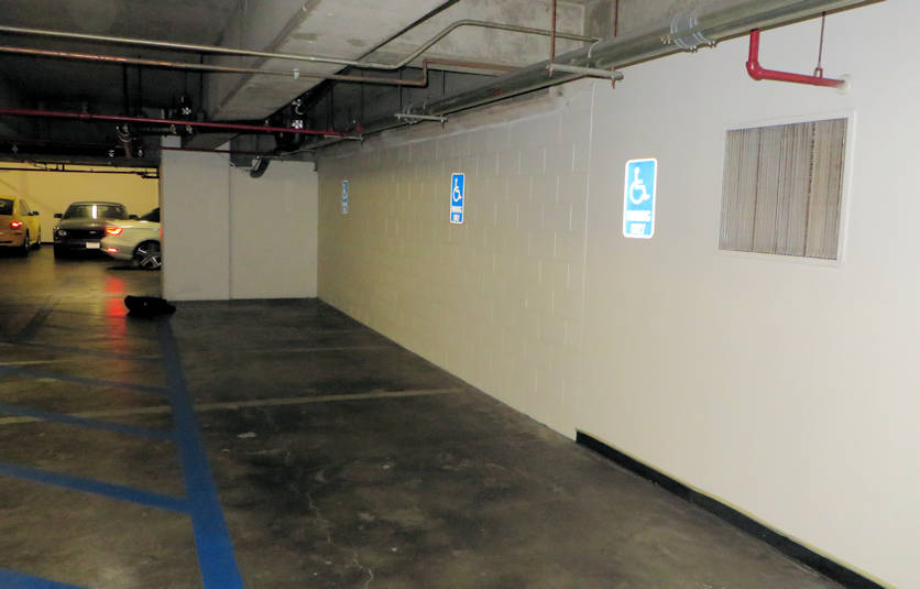
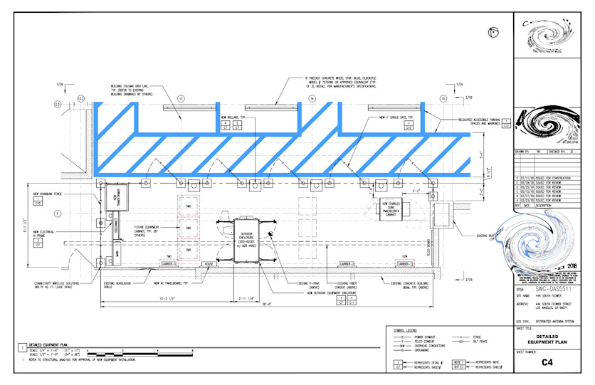
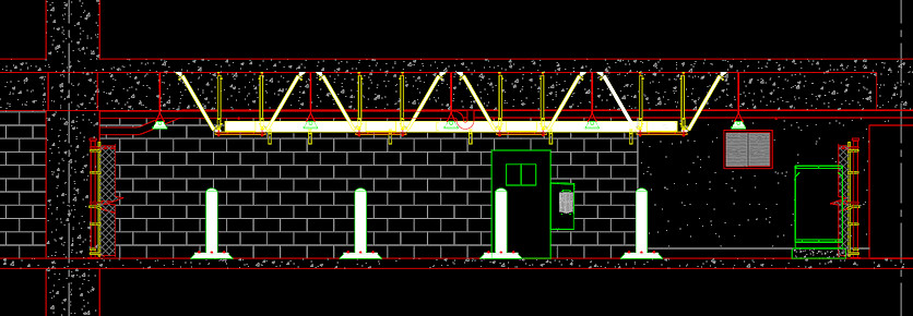
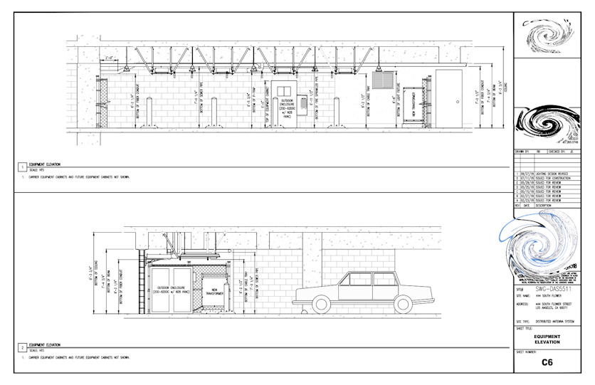
Head-End Equipment Space
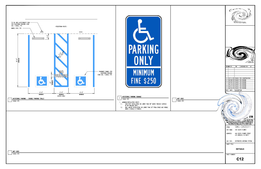
- Relocation of three existing accessible parking stalls.
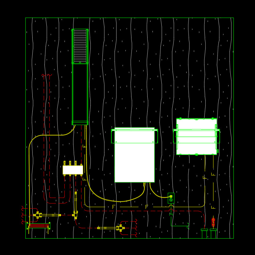
- New chainlink-fenced head-end equipment space on parking level.
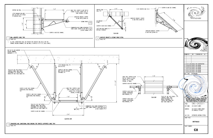
- New overhead cable rack with seismic bracing.
- Equipment layout plan.
- Overhead cable rack layout plan.
- Life safety plan.
- Electrical plan with new AC panelboards connecting to an existing electrical system.
- Grounding plan.
- Lighting plan for new overhead lighting, with photometrics, as well as new AC receptacles.
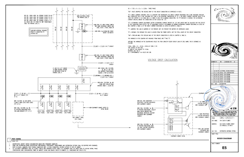
- Electrical riser diagram and AC panel schedules.
Antenna Trunking
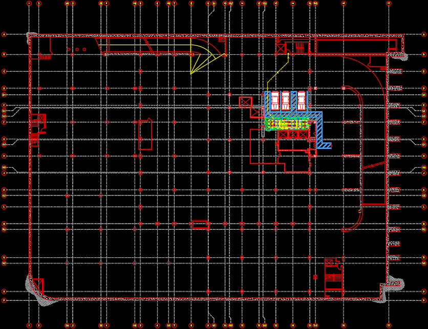
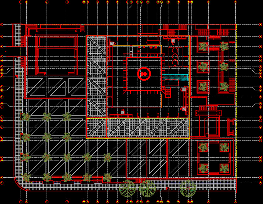
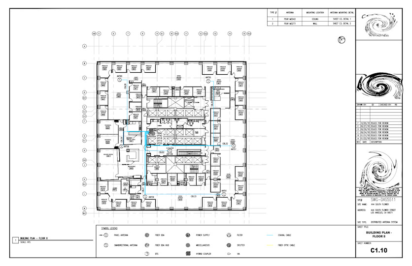
- Building Plans depicting cable routing and antennas throughout building.
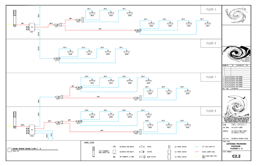
- Antenna Trunking Diagram (riser).
- Antenna Mounting Details.
- Remote Unit Wall Mounting Detail.
Deliverables included:
- Site Survey with Lease Exhibit.
- Permit Drawings (Head-End Design).
- Heat Load calculations.
- Structural Design (floor loading).
- Heat Load Calculations.
- Electrical Survey.
- Structural Assessment (ceiling load, auxiliary framing, cabling).
- Permit Drawings (Trunking Design).
- Review of Gear Submittal Package.
- State of California Title 24 Code Compliance.
|